✅ Future-proofBuilt to keep working — even if the maker walks away.
It works locally over Z-Wave, so it keeps running even if ABUS shuts down the app or the servers. Nothing here ties you to a single company's survival.
Works locally over Z-Wave — keeps running without the maker's cloud
Still in production
Companion app is actively updated
Based on how this device connects (local vs. cloud), whether it’s still sold and supported, and its app / subscription. A guide, not a guarantee.
Connectivity
Z-Wave
Prices
No prices yet — be the first to add one.
Community tags
Be the first to tag this page — tags appear right away. Try a theme, capability, or subject (e.g. WWII, heist, slow burn, time travel, A24).
Community photos
Photos from members
No member photos yet.
Reviews
What members say
Sign in to rate Nexello 3I/3O Hybrid Module and share a photo.
No reviews yet.
Community
Be the first to start a thread about Nexello 3I/3O Hybrid Module
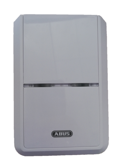
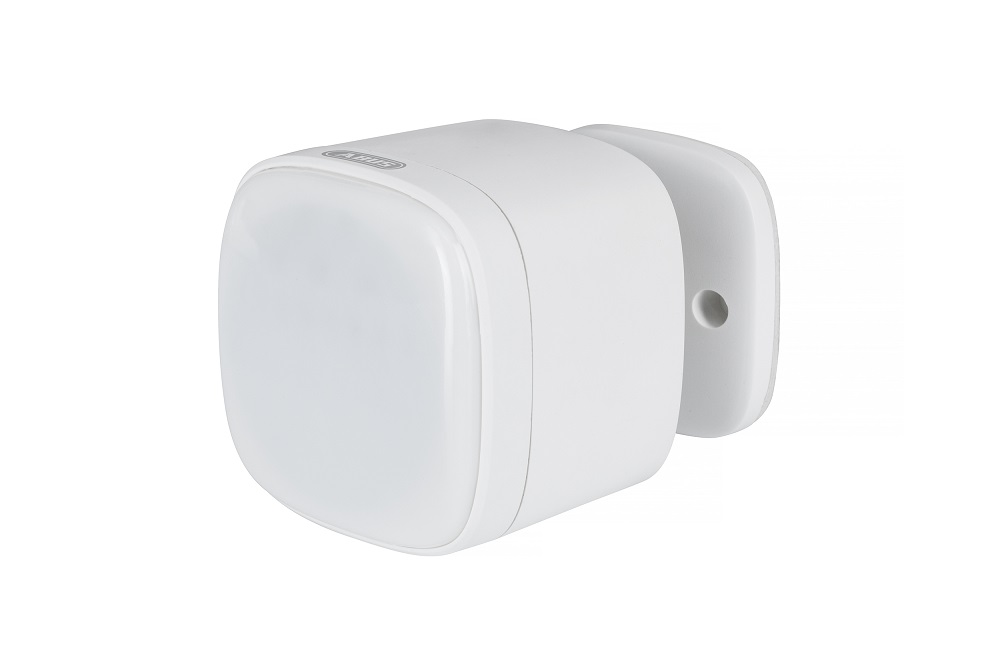
The module is mounted via a bracket, it is tamper protected and has a back-up battery. Three Inputs for the connection of: Analogue sensors with voltage 0~12V Digital sensors with voltage 0~12V Potential-free outputs NC/NO Open Collector Outputs OC Three Outputs for connecting actuators with a maximum of 24VDC SPDT (Single Pole, Double Throw) relay (toggle switch) functions: Configurable timer that automatically switches off after a preset period of time (default is 500 ms) The output can be set to activate automatically when the input terminals (see configuration setting)
Want to buy adds it to your wish list and follows ABUS for updates. I own it adds it to your collection.
The module is mounted via a bracket, it is tamper protected and has a back-up battery. Three Inputs for the connection of: Analogue sensors with voltage 0~12V Digital sensors with voltage 0~12V Potential-free outputs NC/NO Open Collector Outputs OC Three Outputs for connecting actuators with a maximum of 24VDC SPDT (Single Pole, Double Throw) relay (toggle switch) functions: Configurable timer that automatically switches off after a preset period of time (default is 500 ms) The output can be set to activate automatically when the input terminals (see configuration setting)
Hardware platform
SD3502
Short description
The module supports 3 Inputs for max. 12V and 3 Outputs for max. 24V.
Product identifier
PLHA10100
Countries / regions
European Union
Supports smart start
Yes
Certification number
ZC10-20076949
Radio range z wave (m)
40
Configuration parameters
Parameter Number Name Description Format Size Min Value Max Value Default Value Parameter Values 8
Supports explorer frames
Yes
Supported command classes
Identifier Name Key Version COMMAND_CLASS_CONFIGURATION_V4
Controlled command classes
Identifier Name Key Version COMMAND_CLASS_BASIC
Supported multilevel sensors
Multilevel Sensor Type Voltage
Supported notification types
Notification Type Event / State Home Security
Value 4 battery type value aaa association groups
Group Number Maximum Nodes Supported End Point ID Group Name Description 4
From to description 0 0 switched permanently 1 255 adjustable duration from 1 255 in seconds 7 relay output 2 switching time setting for the duration of the switching time when the relay output is switched. 2 1 0 255 5 from to description 0 0 relay output is permanently switched 1 255 adjustable duration from 1 255 in 100ms steps 9 signal input 2 voltage high threshold setting, from which voltage rise the signal input is triggered 2 1 0 255 25 from to description 0 255 adjustable from 0 255 in 100m v steps (25 = 2500m v = 2.5 v) 2 relay output 1 switching time setting for the duration of the switching time when the relay output is switched. 2 1 0 255 5 from to description 0 0 relay output is permanently switched 1 255 adjustable duration from 1 255 in 100ms steps 3 signal input 1 switching time at association group 2 setting for the duration of the switching time at association group 2 when signal input is triggered. 2 1 0 255 180 from to description 0 0 switched permanently 1 255 adjustable duration from 1 255 in seconds 4 signal input 1 voltage high threshold setting, from which voltage rise the signal input is triggered 2 1 0 255 25 from to description 0 255 adjustable from 0 255 in 100m v steps (25 = 2500m v = 2.5 v) 5 signal input 1 voltage low threshold setting of the voltage drop below which the signal input is triggered 2 1 0 255 10 from to description 0 255 adjustable from 0 255 in 100m v steps (10 = 1000m v = 1.0 v) 10 signal input 2 voltage low threshold setting of the voltage drop below which the signal input is triggered 2 1 0 255 10 from to description 0 255 adjustable from 0 255 in 100m v steps (10 = 1000m v = 1.0 v) texts