✅ Future-proofBuilt to keep working — even if the maker walks away.
It works locally over Z-Wave, so it keeps running even if FIBARO shuts down the app or the servers. Nothing here ties you to a single company's survival.
Works locally over Z-Wave — keeps running without the maker's cloud
Still in production
Based on how this device connects (local vs. cloud), whether it’s still sold and supported, and its app / subscription. A guide, not a guarantee.
Connectivity
Z-Wave
Prices
No prices yet — be the first to add one.
Community tags
Be the first to tag this page — tags appear right away. Try a theme, capability, or subject (e.g. WWII, heist, slow burn, time travel, A24).
Community photos
Photos from members
No member photos yet.
Reviews
What members say
Sign in to rate RGBW Controller 2 and share a photo.
No reviews yet.
Community
Be the first to start a thread about RGBW Controller 2
Threads post into the FIBARO community forum.
Sign in to start a thread in the FIBARO community.
Edit history
Loading edit history…
Certified
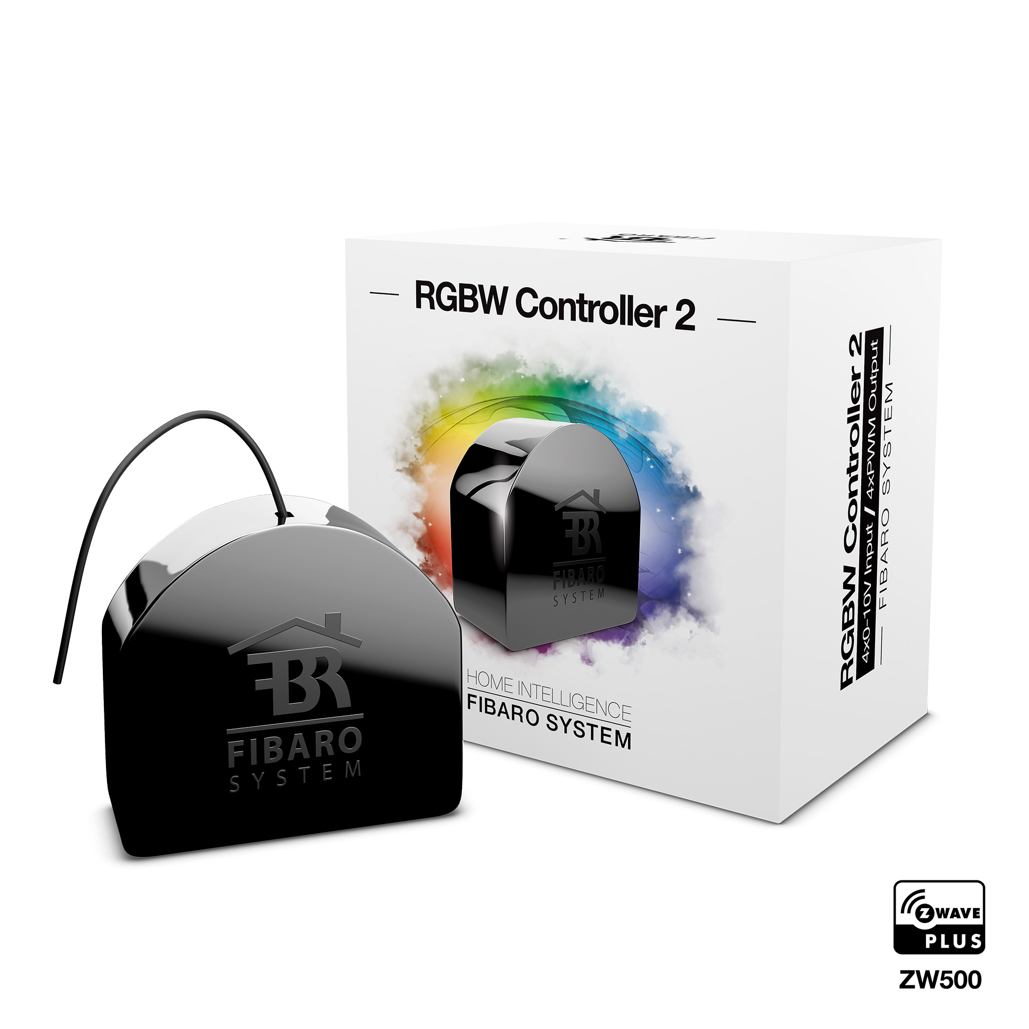
FIBARO RGBW Controller 2 is a universal, Z-Wave Plus compatible RGB/RGBW controller. FIBARO RGBW Controller 2 uses PWM output signal, allowing it to control LED, RGB, RGBW strips, halogen lights and other resistive loads. It can also measure active power and energy consumed by the load. Controlled devices may be powered by 12 or 24V DC. Inputs support momentary/toggle switches and 0-10V analog sensors, like temperature sensors, humidity sensors, light sensors etc. Main features of FIBARO RGBW Controller: • Compatible with any certified Z-Wave or Z-Wave Plus controller. • Supports Z-Wave network Security Modes: S0 with AES-128 encryption and S2 Authenticated with PRNG-based encryption. • Works as a Z-Wave signal repeater. • Allows for controlling: » RGB/RGBW LED strip, » one-color LED strips, » halogen lights, » other compliant resistive loads. • Allows for connecting to inputs: » switches/buttons, » 0-10V analog sensors or potentiometers. • Active power and energy metering.
Want to buy adds it to your wish list and follows FIBARO for updates. I own it adds it to your collection.
FIBARO RGBW Controller 2 is a universal, Z-Wave Plus compatible RGB/RGBW controller. FIBARO RGBW Controller 2 uses PWM output signal, allowing it to control LED, RGB, RGBW strips, halogen lights and other resistive loads. It can also measure active power and energy consumed by the load. Controlled devices may be powered by 12 or 24V DC. Inputs support momentary/toggle switches and 0-10V analog sensors, like temperature sensors, humidity sensors, light sensors etc. Main features of FIBARO RGBW Controller: • Compatible with any certified Z-Wave or Z-Wave Plus controller. • Supports Z-Wave network Security Modes: S0 with AES-128 encryption and S2 Authenticated with PRNG-based encryption. • Works as a Z-Wave signal repeater. • Allows for controlling: » RGB/RGBW LED strip, » one-color LED strips, » halogen lights, » other compliant resistive loads. • Allows for connecting to inputs: » switches/buttons, » 0-10V analog sensors or potentiometers. • Active power and energy metering.
Hardware platform
ZM5101
Short description
FIBARO RGBW Controller 2 is a universal, Z-Wave Plus compatible RGB/RGBW controller.
Product identifier
FGRGBW-442
Countries / regions
Australia
Supports smart start
Yes
Certification number
ZC10-19096752
Radio range z wave (m)
40
Configuration parameters
Parameter Number Name Description Format Size Min Value Max Value Default Value Parameter Values 1
Supports explorer frames
Yes
Supported command classes
Identifier Name Key Version COMMAND_CLASS_FIRMWARE_UPDATE_MD_V4
Controlled command classes
Identifier Name Key Version COMMAND_CLASS_SWITCH_COLOR_V3
Supported multilevel sensors
Multilevel Sensor Type General purpose
Supported notification types
Notification Type Event / State Power Management
Supported / controlled meter types
Meter Type Rate Type Description Electric meter
Value antique brass electric load type sensors supported meter type supported notification types association groups
Group Number Maximum Nodes Supported End Point ID Group Name Profile Description 1
From to description 0 0 device remains switched off 1 1 device restores the state from before the power failure 23 input 4 operating mode this parameter allows to choose mode of 4th input (in4). change it depending on connected device. 0 1 0 0 2 from to description 0 0 analog input without internal pull up (sensor multilevel) 1 1 analog input with internal pull up (sensor multilevel) 2 2 momentary switch (central scene) 3 3 toggle switch: switch state on every input change (central scene) 4 4 toggle switch: contact closed – on, contact opened – off (central scene) 31 alarm configuration 2nd slot this parameter determines to which alarm frames and how the device should react. the parameters consist of 4 bytes, three most significant bytes are set according to the official z wave protocol specification. x – channels summarized: 1/2/3/4 channel are equal to values 1/2/4/8. y – sequence number: 1 10 (parameter 157). 0 4 0 0 0 from to description 1 1 [msb] – notification type 2 2 notification status 3 3 event/state parameters 4 4 [lsb] – action: 0x00 – no reaction, 0x0 x – turn off selected channel, 0x1 x – turn on selected channel, 0x2 x – blink selected channel, 0x3 y – activate alarm sequence 41 input 2 sent scenes this parameter defines which actions result in sending scene id and attribute assigned to them. parameter is relevant only if parameter 21 is set to 2, 3 or 4. 0 1 0 0 0 from to description 1 1 key pressed 1 time 2 2 key pressed 2 times 4 4 key pressed 3 times 8 8 key hold down and key released 42 input 3 sent scenes this parameter defines which actions result in sending scene id and attribute assigned to them. parameter is relevant only if parameter 22 is set to 2, 3 or 4. 0 1 0 0 0 from to description 1 1 key pressed 1 time 2 2 key pressed 2 times 4 4 key pressed 3 times 8 8 key hold down and key released 43 input 4 sent scenes this parameter defines which actions result in sending scene id and attribute assigned to them. parameter is relevant only if parameter 23 is set to 2, 3 or 4. 0 1 0 0 0 from to description 1 1 key pressed 1 time 2 2 key pressed 2 times 4 4 key pressed 3 times 8 8 key hold down and key released 63 analog inputs reports on change this parameter defines minimal change (from the last reported) of analog input voltage that results in sending new report. parameter is relevant only for analog inputs (parameter 20, 21, 22 or 23 set to 0 or 1). analog inputs reports (sensor multilevel) are sent no often than every 30 seconds. 0 2 0 0 5 from to description 0 0 reporting on change disabled 1 100 (0.1 10 v, 0.1 v step) 65 energy reports on change this parameter determines the minimum change in consumed energy that will result in sending new energy report to the main controller. energy reports are sent no often than every 30 seconds. 0 2 0 0 10 from to description 0 0 reports are disabled 1 500 (0.01 5 k wh) change in energy 150 inputs led colour control mode this parameter determines how connected switches control led strips. 0 1 0 0 0 from to description 0 0 rgbw mode (every input controls output with the same number, in1‑out1, in2‑out2, in3‑out3, in4‑out4) 1 1 hsb and white mode (inputs works in hsb color model, in1‑h (hue), in2‑s (saturation), in3‑b (brightness), in4‑white (out4) 151 local control transition time this parameter determines time of smooth transition between 0% and 100% when controlling with connected switches. 0 2 0 0 3 from to description 0 0 instantly 1 127 (1s 127s, 1s step) 128 254 (1min 127min, 1min step) 152 remote control transition time this parameter determines time of smooth transition between initial and target state when controlling via z wave network. 0 2 0 0 3 from to description 0 0 instantly 1 127 (1s 127s, 1s step) 128 254 (1min 127min, 1min step) 154 on frame value for single click this parameter defines value sent to devices in association groups. the parameters consist of 4 bytes, each byte reserved for separate channel, from least significant (in1) to most significant (in4). 0 4 0 0 0 from to description 0 99 value sent to devices 255 255 value sent to devices 155 off frame value for single click this parameter defines value sent to devices in association groups. the parameters consist of 4 bytes, each byte reserved for separate channel, from least significant (in1) to most significant (in4). 0 4 0 0 0 from to description 0 99 value sent to devices 255 255 value sent to devices 156 on frame value for double click this parameter defines value sent to devices in association groups. the parameters consist of 4 bytes, each byte reserved for separate channel, from least significant (in1) to most significant (in4). 0 4 0 0 0 from to description 0 99 value sent to devices 255 255 value sent to devices 157 start programmed sequence setting this parameter will start programmed sequence with selected number. user can define own sequences via controller. 0 1 0 0 0 from to description 0 0 sequence inactive 1 5 user defined sequence 6 6 fireplace sequence 7 7 storm sequence 8 8 rainbow sequence 9 9 aurora sequence 10 10 police (red white blue) sequence texts