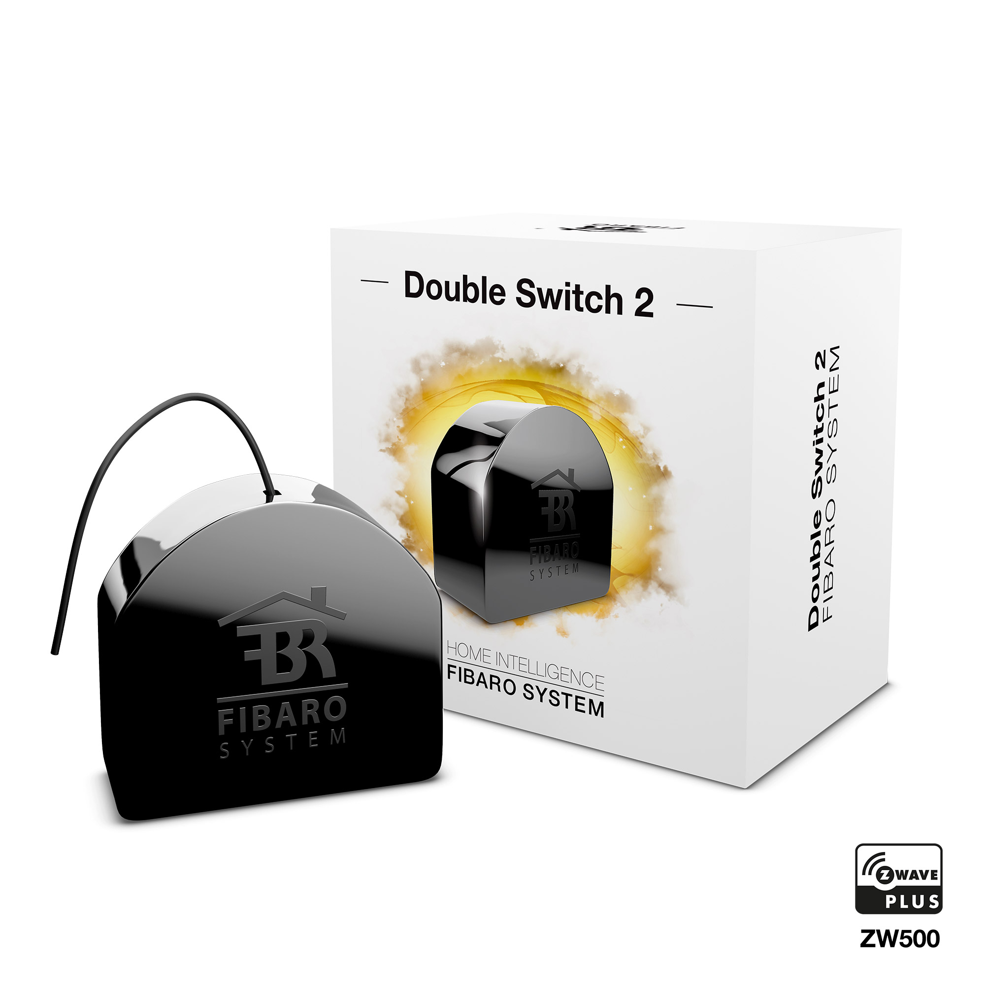
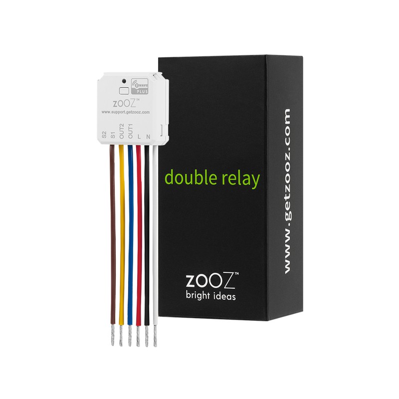
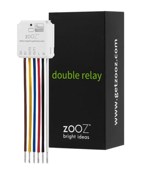
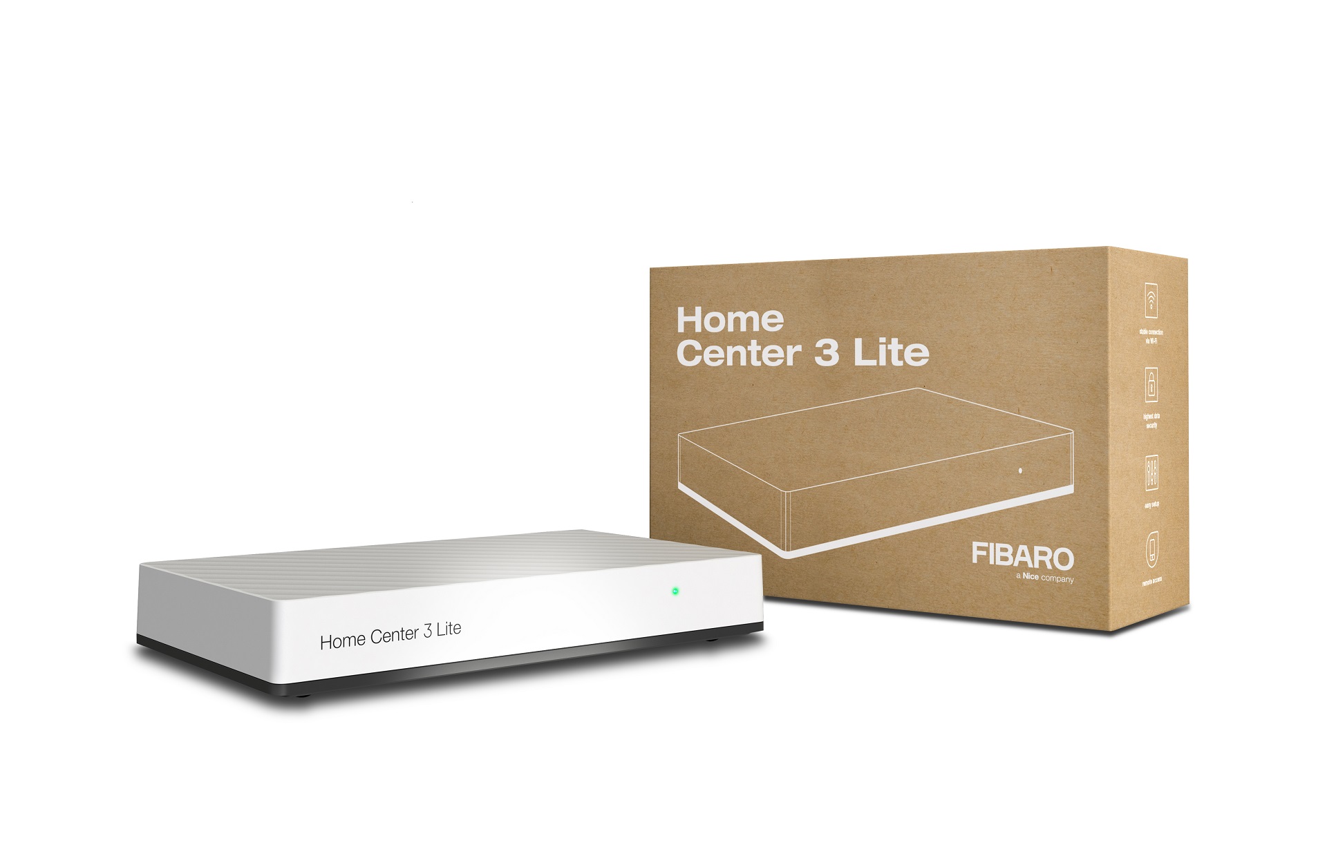
The remotely operated FIBARO Double Switch 2 is designed to turn two electrical devices on and off and to measure their power and energy consumption. The compact size of the device makes it the world's smallest of its type and allows for the product to be installed in wall switch boxes or housings. FIBARO Double Switch 2 can be controlled either via Z-Wave network or with a wall switch through a direct connection.
Want to buy adds it to your wish list and follows FIBARO for updates. I own it adds it to your collection.
✅ Future-proofBuilt to keep working — even if the maker walks away.
It works locally over Z-Wave, so it keeps running even if FIBARO shuts down the app or the servers. Nothing here ties you to a single company's survival.
Works locally over Z-Wave — keeps running without the maker's cloud
Still in production
Based on how this device connects (local vs. cloud), whether it’s still sold and supported, and its app / subscription. A guide, not a guarantee.
Connectivity
Z-Wave
Prices
No prices yet — be the first to add one.
Community tags
Be the first to tag this page — tags appear right away. Try a theme, capability, or subject (e.g. WWII, heist, slow burn, time travel, A24).
Community photos
Photos from members
No member photos yet.
Reviews
What members say
Sign in to rate FIBARO Double Switch 2 and share a photo.
No reviews yet.
Community
Be the first to start a thread about FIBARO Double Switch 2
Threads post into the FIBARO community forum.
Sign in to start a thread in the FIBARO community.
Edit history
Loading edit history…
Firmware
Current version HW: 3 FW: 3.03
Specifications
Overview
Company
FIBARO
Category
Plug Switch
Device type
On/Off Power Switch
Connectivity
Standard / protocol
Z-Wave
Connectivity
Z-Wave
Transport
Z-Wave
Spec version
6.51.07
Z-Wave frequency
US: 916.00MHz, 908.40MHz
Certification & compliance
Certificate ID
ZC10-18015925
Firmware & software
Firmware version
HW: 3 FW: 3.03
Hardware version
ZM5101
Identity & commercial
Model number
FGS-223
Lifecycle
Status
Active
More specs
Name
FIBARO Double Switch 2
Brand
FIBARO
Features
Feature Values Color
Documents
Category Description File Manual_Primary_Lang
Role type
ROLE_TYPE_SLAVE_ALWAYS_ON
User icon
0x0700
Categories
Energy Meters, All Lighting Devices, On/Off Switches/Devices
Product id
0x2000
Device type
On/Off Power Switch
Oem version
HW: 3 FW: 3.03
Library type
SLAVE_ENHANCED_232
Supports nwi
Yes
Installer icon
0x0700
Similar Plug Switch
Current-generation and recently-released alternatives in the same category.
The remotely operated FIBARO Double Switch 2 is designed to turn two electrical devices on and off and to measure their power and energy consumption. The compact size of the device makes it the world's smallest of its type and allows for the product to be installed in wall switch boxes or housings. FIBARO Double Switch 2 can be controlled either via Z-Wave network or with a wall switch through a direct connection.
Hardware platform
ZM5101
Short description
FIBARO Double Switch 2 is designed to turn two electrical devices on and off and to measure their power and energy consumption.
Product identifier
FGS-223
Countries / regions
United States of America
Certification number
ZC10-18015925
Radio range z wave (m)
40
Configuration parameters
Parameter Number Name Description Format Size Min Value Max Value Default Value Parameter Values 10
Supports explorer frames
Yes
Supported command classes
Identifier Name Key Version COMMAND_CLASS_POWERLEVEL
Controlled command classes
Identifier Name Key Version COMMAND_CLASS_BASIC
Supported notification types
Notification Type Event / State Heat Alarm
Supported / controlled meter types
Meter Type Rate Type Description Electric meter
Value black switch load capacity current value 6 a per channel resistive loads, 3 a per channel tungsten loads, 9.5 a overall resistive loads switch load capacity watts value up to 2400 w loads controlled value 2 supported meter type value electric energy supported notification types value heat alarm power management association groups
Group Number Maximum Nodes Supported End Point ID Description 2
From to description 0 0 standard operation 1 1 delay on function 2 2 delay off function 3 3 auto on function 4 4 auto off function 5 5 flash function 11 first channel reaction to switch for delay/auto on/off modes this parameter determines how the device in timed mode reacts to pushing the switch connected to the s1 terminal. 0 cancel mode and set target state 1 no reaction to switch mode runs until it ends 2 reset timer start counting from the beginning 0 1 0 0 0 from to description 0 0 cancel mode and set target state 1 1 no reaction to switch mode runs until it ends 2 2 reset timer start counting from the beginning 17 second channel time parameter for delay/auto on/off modes this parameter allows to set time parameter used in timed modes. 0 (0.1s), 1 32000 (1 32000s, 1s step) time parameter 0 2 0 0 50 from to description 0 0 0.1s 1 32000 1 32000s, 1s step 31 s1 switch switch on value sent to 2nd and 3rd association groups this parameter defines value sent with switch on command to devices associated in 2nd and 3rd association group. 0 255 sent value note *hold and release is inactive when parameter 20 is set to 1 or 2. **double click is inactive when parameter 20 is set to 1. 0 2 0 0 255 9 restore state after power failure this parameter determines if the device will return to state prior to the power failure after power is restored. 0 the device does not save the state prior to the power failure and returns to „off” position 1 the device restores its state prior to the power failure 0 1 0 0 1 from to description 0 0 the device does not save the state prior to the power failure and returns to „off” position 1 1 the device restores its state prior to the power failure 41 reaction to flood alarm this parameter determines how the device will react to flood alarm frame. 0 alarm frame is ignored 1 turn on after receiving the alarm frame 2 turn off after receiving the alarm frame 3 flash after receiving the alarm frame 0 1 0 0 2 from to description 0 0 alarm frame is ignored 1 1 alarm frame is ignored 2 2 turn off after receiving the alarm frame 3 3 flash after receiving the alarm frame 42 reaction to co/co2/smoke alarm this parameter determines how the device will react to co, co2 or smoke frame. 0 alarm frame is ignored 1 turn on after receiving the alarm frame 2 turn off after receiving the alarm frame 3 flash after receiving the alarm frame 0 1 0 0 3 from to description 0 0 alarm frame is ignored 1 1 turn on after receiving the alarm frame 2 2 turn off after receiving the alarm frame 3 3 flash after receiving the alarm frame 43 reaction to heat alarm this parameter determines how the device will react to heat alarm frame. 0 alarm frame is ignored 1 turn on after receiving the alarm frame 2 turn off after receiving the alarm frame 3 flash after receiving the alarm frame 0 1 0 0 1 from to description 0 0 alarm frame is ignored 1 1 turn on after receiving the alarm frame 2 2 turn off after receiving the alarm frame 3 3 flash after receiving the alarm frame 44 flashing alarm duration this parameter allows to set duration of flashing alarm mode. 1 32000 (1 32000s, 1s step) duration 0 2 0 0 600 from to description 1 32000 1 32000s, 1s step 51 first channel minimal time between power reports this parameter determines minimum time that has to elapse before sending new power report to the main controller. 0 periodic reports are disabled 1 120 (1 120s) report interval 0 1 0 0 10 from to description 0 0 periodic reports are disabled 1 120 (1 120s) report interval 53 first channel energy reports this parameter determines the minimum change in consumed energy that will result in sending new energy report to the main controller. 0 reports are disabled 1 32000 (1 32000 wh) change in energy 0 2 0 0 100 from to description 0 0 reports are disabled 1 32000 1 32000 (1 32000 wh) change in energy 55 second channel minimal time between power reports this parameter determines minimum time that has to elapse before sending new power report to the main controller. 0 periodic reports are disabled 1 120 (1 120s) report interval 0 1 0 0 10 from to description 0 0 periodic reports are disabled 1 120 (1 120s) report interval 57 second channel energy reports this parameter determines the minimum change in consumed energy that will result in sending new energy report to the main controller. 0 reports are disabled 1 32000 (1 32000 wh) change in energy 0 2 0 0 100 from to description 0 0 reports are disabled 1 32000 1 32000 (1 32000 wh) change in energy 58 periodic power reports this parameter determines in what time intervals the periodic power reports are sent to the main controller. 0 periodic reports are disabled 1 32000 (1 32000s) report interval 0 2 0 0 3600 from to description 0 0 periodic reports are disabled 1 32000 (1 32000s) report interval 59 periodic energy reports this parameter determines in what time intervals the periodic energy reports are sent to the main controller. 0 periodic reports are disabled 1 32000 (1 32000s) report interval 0 2 0 0 3600 from to description 0 0 periodic reports are disabled 1 32000 (1 32000s) report interval 60 measuring energy consumed by the device itself this parameter determines whether energy metering should include the amount of energy consumed by the device itself. results are being added to energy reports for first endpoint. 0 function inactive 1 function activate 0 1 0 0 0 from to description 0 0 function inactive 1 1 function activate texts