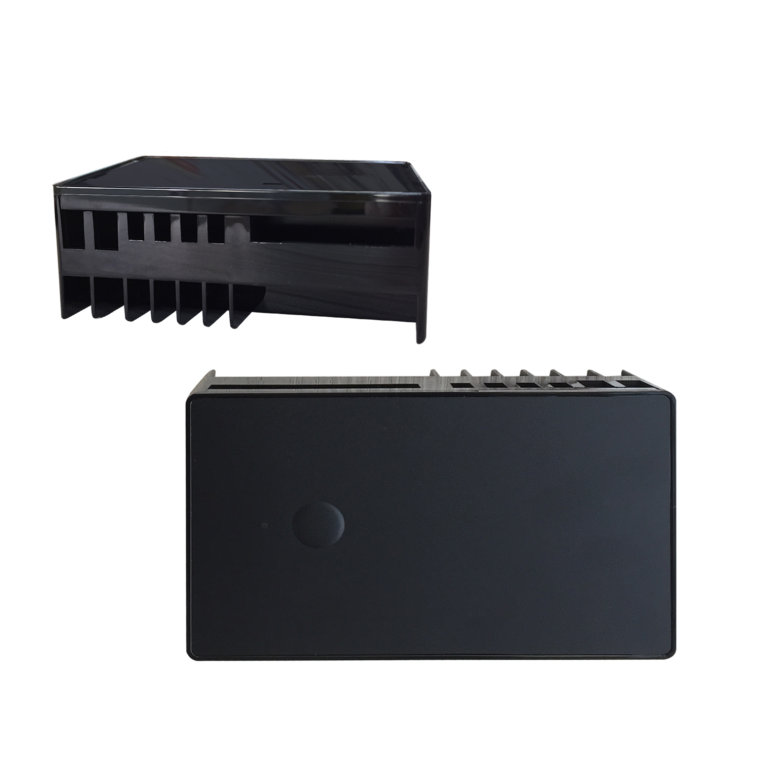
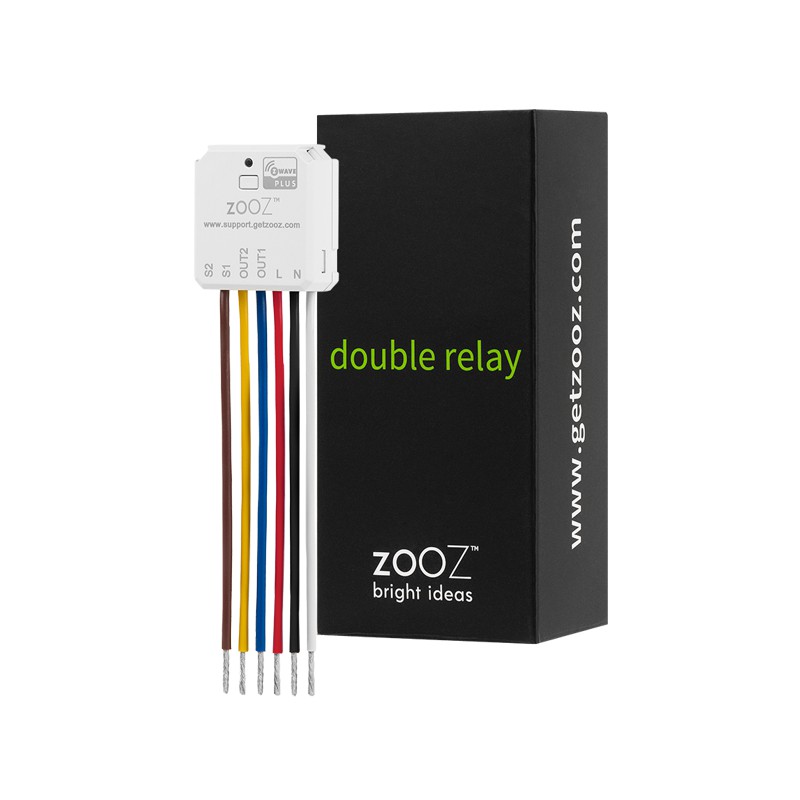
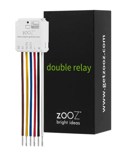
Long descriptionThe remotely operated FIBARO Double Smart Module is designed to turn electrical devices or circuits on and off. Double Smart Module allows to control two devices or circuits. The compact size of the device allows for the product to be installed in the housings of other devices. The devices can be controlled either via the Z-Wave™ network or with buttons connected directly to them. From to description 0 255 [lsb] – action 256 65535 event/state parameters 65536 16777215 notification status 16777216 2147483647 [msb] – notification type 1 remember relays state this parameter determines the state of relays after power supply failure (e.g. power outage). for auto off and flashing modes the parameter is not relevant and the relay will always remain switched off. 1 1 0 2 1 from to description 0 0 relays remain switched off after restoring power 1 1 restore remembered state of relays after restoring power 2 2 restore remembered state of relays after restoring power, but for toggle switches (parameter 20/21 set to 1) set the same state as the current state of the switches 24 inputs orientation this parameter allows reversing operation of s1 and s2 inputs without changing the wiring. use in case of incorrect wiring. 1 1 0 1 0 from to description 1 1 reversed (s1 2nd channel, s2 1st channel) 0 0 default (s1 1st channel, s2 2nd channel) 25 outputs orientation this parameter allows reversing operation of q1 and q2 outputs without changing the wiring. use in case of incorrect wiring. 1 1 0 1 0 from to description 0 0 default (q1 1st channel, q2 2nd channel) 1 1 reversed (q1 2nd channel, q2 1st channel) 152 first channel reaction to input change in delayed/auto off modes this parameter determines how the device reacts when changing state of s1 input in timed modes for first channel. 1 1 0 2 0 from to description 0 0 cancel mode and set default state 1 1 no reaction, mode runs until it ends 2 2 reset timer, start counting time from the beginning 153 second channel – reaction to input change in delayed/ auto off modes this parameter determines how the device reacts when changing state of s2 input in timed modes for second channel. 1 1 0 2 0 from to description 0 0 cancel mode and set default state 1 1 no reaction, mode runs until it ends 2 2 reset timer, start counting time from the beginning 154 first channel – time parameter for delayed/auto off and flashing modes this parameter allows to set time parameter used in timed modes for first channel. for delayed/ auto off modes it determines duration, for flashing mode it determines cycle period. 1 2 0 32000 5 from to description 0 0 0.1 seconds 1 32000 0.1 3200 seconds, 0.1s step 157 s1 input – switch off value sent to 2nd association group this parameter defines value sent with switch off command to devices in 2nd association group when using s1 input. 1 2 0 255 0 from to description 255 255 turn on with last level 0 0 turn off 1 99 turn on and set level 150 first channel – operating mode this parameter allows to choose operating mode for channel controlled with q/q1 output. for timed modes (value 1, 2 or 3), time is set with parameter 154 and reaction to input change is set with parameter 152. 1 1 0 3 0 from to description 0 0 standard operation 1 1 delayed off 2 2 auto off 3 3 flashing 155 second channel – time parameter for delayed/auto off and flashing modes this parameter allows to set time parameter used in timed modes for second channel. for delayed/auto off modes it determines duration, for flashing mode it determines cycle period. 1 2 0 32000 5 from to description 0 0 0.1 seconds 1 32000 0.1 3200 seconds, 0.1s step 160 s2 input – switch off value sent to 3rd association group this parameter defines value sent with switch off command to devices in 3rd association group when using s2 input. 1 2 0 255 0 from to description 0 0 turn off 1 99 turn on and set level 255 255 turn on with last level 156 para s1 input – switch on value sent to 2nd association group this parameter defines value sent with switch on command to devices in 2nd association group when using s1 input. 1 2 0 255 255 from to description 0 0 turn off 1 99 turn on and set level 255 255 turn on with last level 158 s1 input – double click value sent to 2nd association group this parameter defines value sent with double click command to devices in 2nd association group when using s1 input. 1 2 0 255 99 from to description 1 99 turn on and set level 0 0 turn off 255 255 turn on with last level 163 q2 output type this parameter determines type of q2 output. 1 1 0 1 0 from to description 0 0 normally open (relay contacts opened turned off, closed when turned on) 1 1 normally closed (relay contacts closed turned off, opened when turned on) 159 s2 input – switch on value sent to 3rd association group this parameter defines value sent with switch on command to devices in 3rd association group when using s2 input. 1 2 0 255 255 from to description 0 0 turn off 1 99 turn on and set level 255 255 turn on with last level 161 s2 input – double click value sent to 3rd association group this parameter defines value sent with double click command to devices in 3rd association group when using s2 input. 1 2 0 255 99 from to description 0 0 turn off 1 99 turn on and set level 255 255 turn on with last level 162 q/q1 output type this parameter determines type of q/q1 output. 1 1 0 1 0 from to description 0 0 normally open (relay contacts opened turned off, closed when turned on) 1 1 normally closed (relay contacts closed turned off, opened when turned on) 164 lock simultaneous switching of q1 and q2 outputs when the lock is enabled, both outputs cannot be turned on at the same time. 1 1 0 1 0 from to description 1 1 lock enabled 0 0 lock disabled textsID Description Value 1