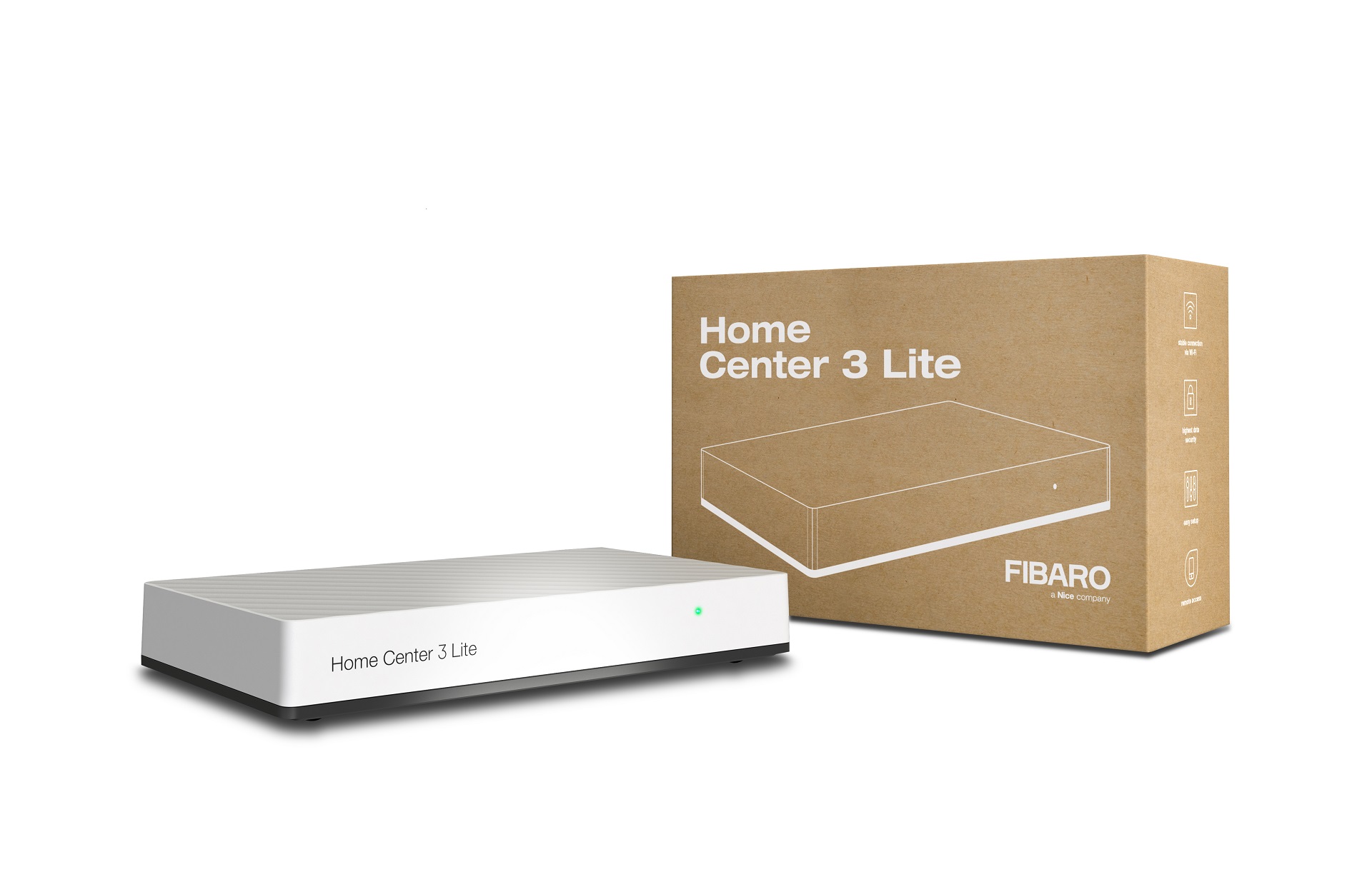
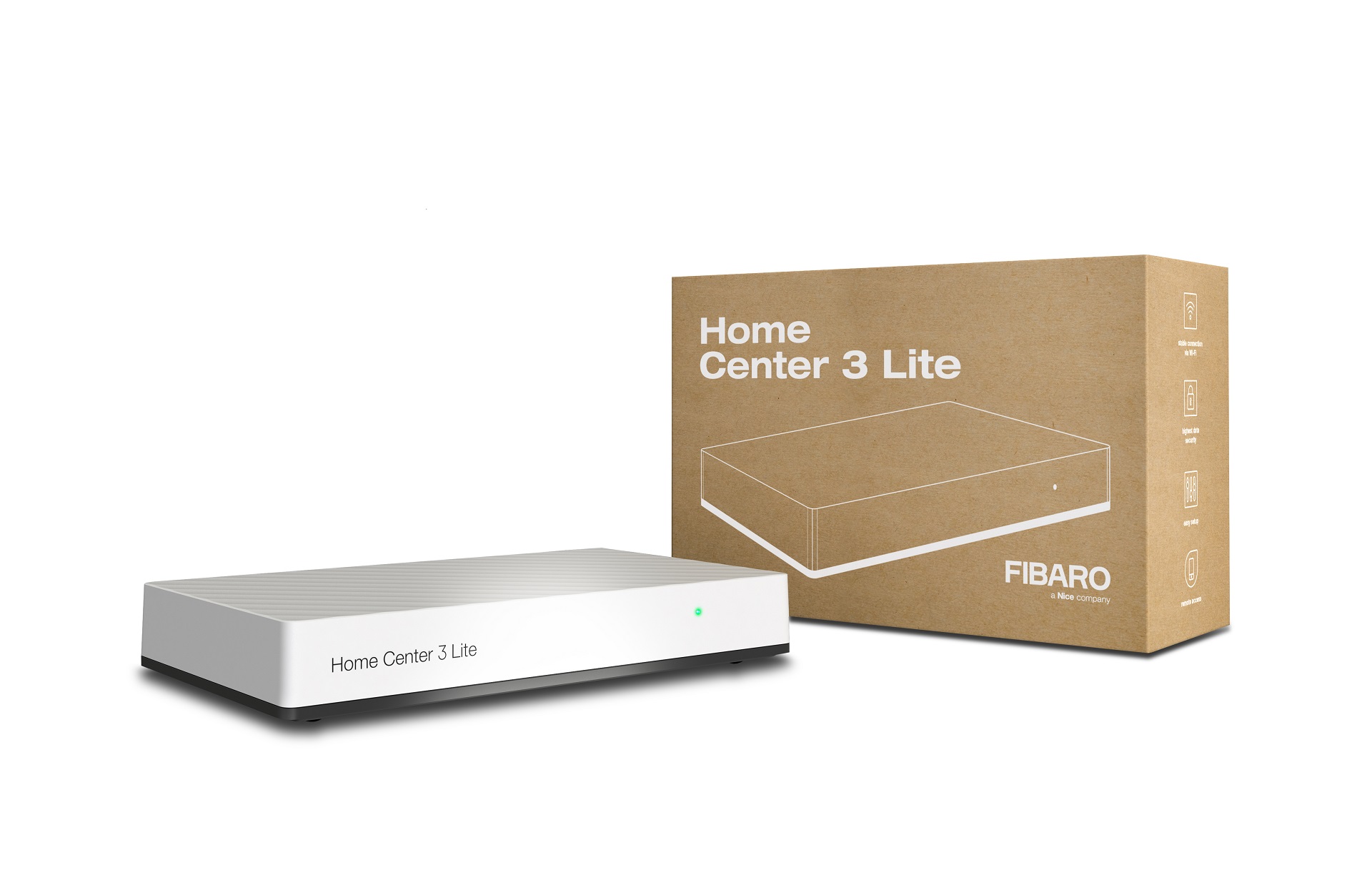
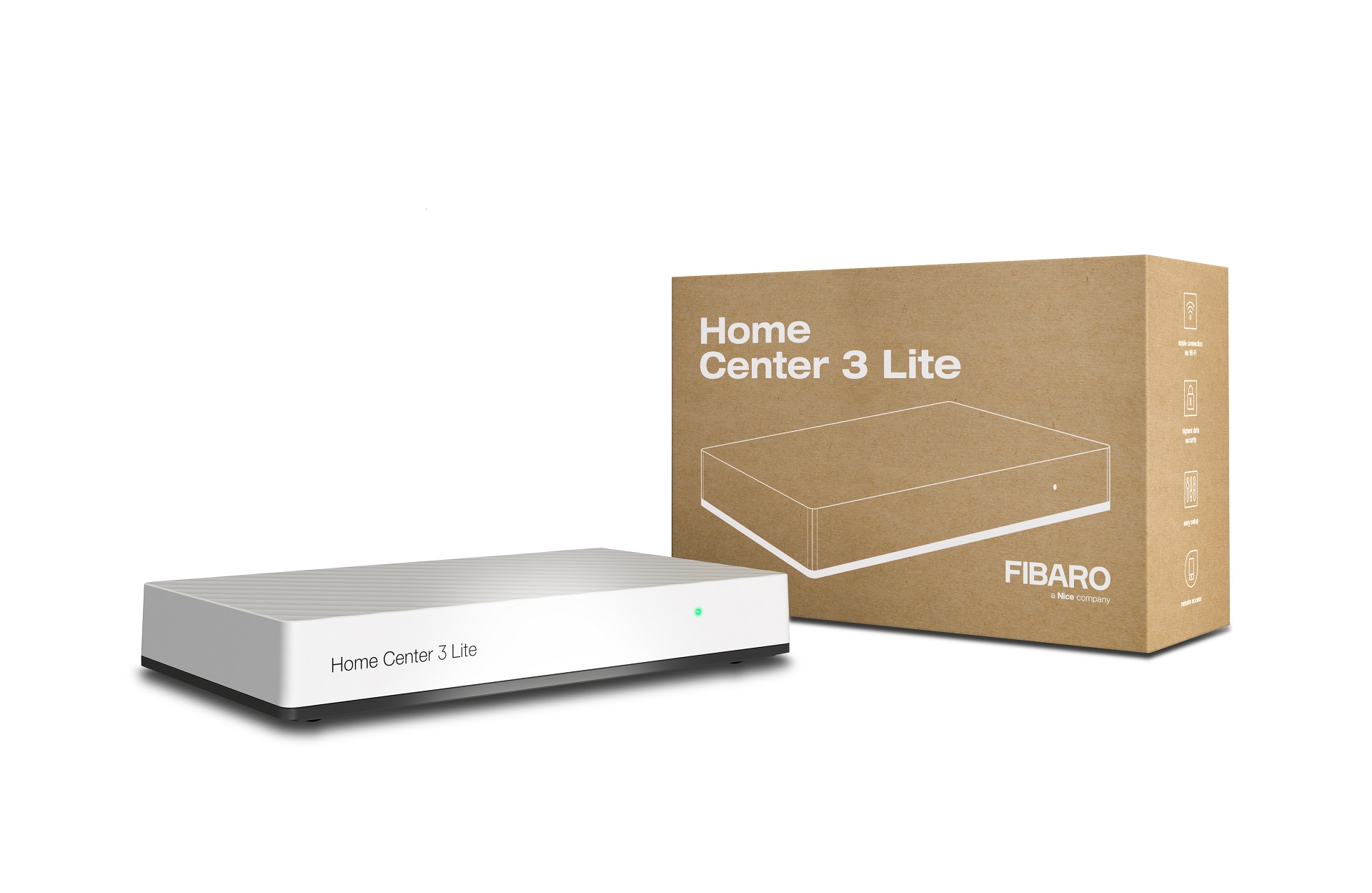
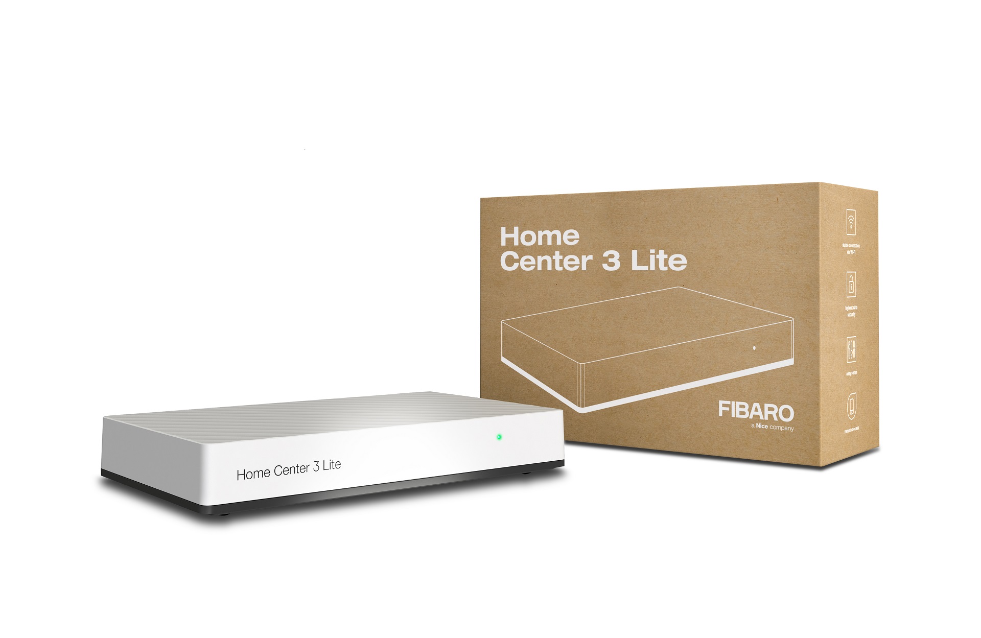
✅ Future-proofBuilt to keep working — even if the maker walks away.
It works locally over Z-Wave, so it keeps running even if FIBARO shuts down the app or the servers. Nothing here ties you to a single company's survival.
Works locally over Z-Wave — keeps running without the maker's cloud
Still in production
Based on how this device connects (local vs. cloud), whether it’s still sold and supported, and its app / subscription. A guide, not a guarantee.
Connectivity
Z-Wave
Prices
No prices yet — be the first to add one.
Community tags
Be the first to tag this page — tags appear right away. Try a theme, capability, or subject (e.g. WWII, heist, slow burn, time travel, A24).
Sign in to start a thread in the FIBARO community.
Edit history
Loading edit history…
Certified
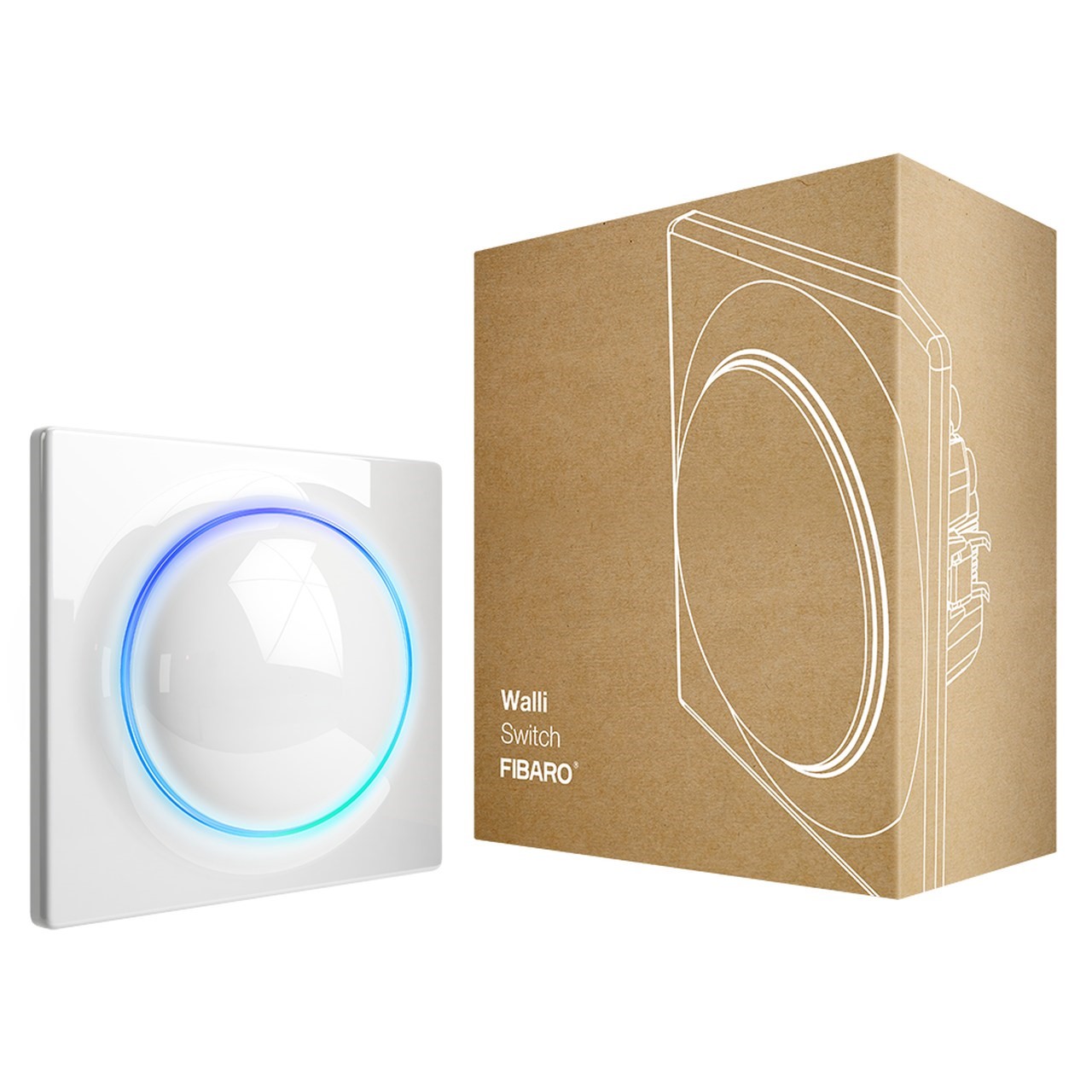
FIBARO Walli Double Switch is a smart wall switch designed to control one or two light sources via Z-Wave network. It measures active power and energy consumed by the controlled load. You can install it with provided cover plate or other compatible. Main features of FIBARO Walli Double Switch: - Can be used with: o Conventional incandescent and halogen light sources, o LED lamps, o Fluorescent lamps, o Electronic transformers (for ELV halogen lamps and LED bulbs), o Ferromagnetic transformers (for MLV halogen lamps). - Can be used with provided cover plate or one of the following: o GIRA – System 55 (Standard 55, E2, Event, Event Clear), o Legrand – Céliane, o Schneider – Odace. - Active power and energy consumption metering. - Supports Z-Wave network Security Modes: S0 with AES-128 encryption and S2 Authenticated with PRNG-based encryption. - Works as Z-Wave signal repeater (all non-battery operated devices within the network will act as repeaters to increase reliability of the network). - May be used with all devices certified with the Z-Wave Plus certificate and should be compatible with such devices produced by other manufacturers.
Want to buy adds it to your wish list and follows FIBARO for updates. I own it adds it to your collection.
FIBARO Walli Double Switch is a smart wall switch designed to control one or two light sources via Z-Wave network. It measures active power and energy consumed by the controlled load. You can install it with provided cover plate or other compatible. Main features of FIBARO Walli Double Switch: - Can be used with: o Conventional incandescent and halogen light sources, o LED lamps, o Fluorescent lamps, o Electronic transformers (for ELV halogen lamps and LED bulbs), o Ferromagnetic transformers (for MLV halogen lamps). - Can be used with provided cover plate or one of the following: o GIRA – System 55 (Standard 55, E2, Event, Event Clear), o Legrand – Céliane, o Schneider – Odace. - Active power and energy consumption metering. - Supports Z-Wave network Security Modes: S0 with AES-128 encryption and S2 Authenticated with PRNG-based encryption. - Works as Z-Wave signal repeater (all non-battery operated devices within the network will act as repeaters to increase reliability of the network). - May be used with all devices certified with the Z-Wave Plus certificate and should be compatible with such devices produced by other manufacturers.
Hardware platform
ZM5101
Short description
FIBARO Walli Double Switch is a smart wall switch designed to control one or two light sources via Z-Wave network.
Product identifier
FGWDSEU-221
Countries / regions
European Union
Supports smart start
Yes
Certification number
ZC10-19056514
Radio range z wave (m)
40
Configuration parameters
Parameter Number Name Description Format Size Min Value Max Value Default Value Parameter Values 2
Supports explorer frames
Yes
Supported command classes
Identifier Name Key Version COMMAND_CLASS_FIRMWARE_UPDATE_MD_V4
Controlled command classes
Identifier Name Key Version COMMAND_CLASS_BASIC
Supported notification types
Notification Type Event / State Power Management
Supported / controlled meter types
Meter Type Rate Type Description Electric meter
Value push button color value white electric load type value incandescent fluorescent led loads controlled value 4 supported meter type value electric energy supported notification types value power management system switch load capacity current value 13 a per one channel; 16 a total association groups
Group Number Maximum Nodes Supported End Point ID Description 1
From to description 0 0 function disabled 10 36200 (1.0 3620.0 w, step 0.1 w) – power threshold 3 second channel – overload safety switch this function allows to turn off the controlled device in case of exceeding the defined power. controlled device can be turned back on via button or sending a control frame. 0 4 0 0 0 from to description 0 0 function disabled 10 36200 (1.0 3620.0 w, step 0.1 w) – power threshold 10 led frame – power limit this parameter determines maximum active power. exceeding it results in the led frame flashing violet. function is active only when parameter 11 is set to 8 or 9. 0 4 0 0 30000 from to description 500 30000 (50.0 3000.0 w, step 0.1 w) – power threshold 11 led frame – colour when on this parameter defines the led colour when thedevice is on. when set to 8 or 9, led frame colour will change depending on he measured power and parameter 10. other colours are set permanently and do not depend on power consumption. 0 1 0 0 1 from to description 0 0 led disabled 1 1 white 2 2 red 3 3 green 4 4 blue 5 5 yellow 6 6 cyan 7 7 magenta 8 8 colour changes smoothly depending on measured power 9 9 colour changes in steps depending on measured power 24 buttons orientation this parameter allows reversing the operation of the buttons. 0 1 0 0 0 from to description 0 0 default (1st button controls 1st channel, 2nd button controls 2nd channel) 1 1 reversed (1st button controls 2nd channel, 2nd button controls 1st channel) 25 outputs orientation this parameter allows reversing the operation of q1 and q2 without changing the wiring (e.g. in case of invalid connection). changing orientation turns both outputs off. 0 1 0 0 0 from to description 0 0 default (q1 1st channel, q2 2nd channel) 1 1 reversed (q1 2nd channel, q2 1st channel) 31 alarm configuration 2nd slot this parameter determines to which alarm frames and how the device should react. the parameters consist of 4 bytes, three most significant bytes are set according to the official z wave protocol specification. 0 4 0 0 0 from to description 1 1 [msb] – notification type 2 2 notification value 3 3 event/state parameters 4 4 [lsb] – action 41 second button – scenes sent this parameter determines which actions result in sending scene ids assigned to them. values can be combined (e.g. 1+2=3 means that scenes for single and double click are sent). enabling scenes for triple click disables entering the device in learn mode by triple clicking. 0 1 0 0 0 from to description 1 1 key pressed 1 time 2 2 key pressed 2 time 4 4 key pressed 3 time 8 8 key hold down and key released 60 power reports – include self consumption this parameter determines whether the power measurements should include power consumed by the device itself. 0 1 0 0 0 from to description 0 0 self consumption not included 1 1 self consumption included 65 energy reports for first channel – on change this parameter defines minimal change (from the last reported) in measured energy that results in sending new report. 0 2 0 0 10 from to description 0 0 reporting on change disabled 1 500 (0.01 5k wh, 0.01k wh step) – minimal change 67 energy reports for second channel – on change this parameter defines minimal change (from the last reported) in measured energy that results in sending new report. 0 4 0 0 10 from to description 0 0 reporting on change disabled 1 500 (0.01 5k wh, 0.01k wh step) – minimal change 150 first channel – operating mode this parameter allows to choose operating for the 1st channel . 0 1 0 0 0 from to description 0 0 standard operation 1 1 delayed off 2 2 single pulse 1 remember device state this parameter determines how the device will react in the event of power supply failure (e.g. power outage). the parameter is not relevant for outputs set to pulse mode (parameter 150/151 set to 2). 0 1 0 0 1 from to description 1 1 restores remembered state after restoring power 0 0 remains switched off after restoring power 151 second channel – operating mode this parameter allows to choose operating for the 2nd channel. 0 1 0 0 0 from to description 0 0 standard operation 1 1 delayed off 2 2 single pulse 152 first channel reaction to switch for delayed off / pulse modes this parameter determines how the device in timed mode reacts to pushing the button for 1st channel. the parameter is relevant only for button toggles modes (parameter 20 set to 1 or 3). 0 1 0 0 0 from to description 0 0 cancel mode and set default state 1 1 no reaction mode runs until it ends 2 2 reset timer start counting from the beginning 153 second channel reaction to switch for delayed off / pulse modes this parameter determines how the device in timed mode reacts to pushing the button for 2nd channel. the parameter is relevant only for button toggles modes (parameter 20 set to 1 or 3). 0 1 0 0 0 from to description 0 0 cancel mode and set default state 1 1 no reaction mode runs until it ends 2 2 reset timer start counting from the beginning 154 first channel time parameter for delayed off / pulse modes this parameter allows to set time parameter used in timed modes for 1st channel (parameter 150). delay time for switching off or duration of the pulse. 0 2 0 0 50 from to description 0 0 0.1 second 1 32000 (1 32000s, 1s step) – time parameter 155 second channel time parameter for delayed off / pulse modes this parameter allows to set time parameter used in timed modes for 2nd channel (parameter 151). delay time for switching off or duration of the pulse. 0 2 0 0 50 from to description 0 0 0.1 second 1 32000 (1 32000s, 1s step) – time parameter 156 first channel – switch on value sent to 2nd and 3rd association groups this parameter defines value sent with switch on command to devices associated in 2nd and 3rd association group for manual changes of endpoint 1 state. 0 2 0 0 255 from to description 0 99 2nd association group 255 255 3rd association group 157 first channel – switch off value sent to 2nd and 3rd association groups this parameter defines value sent with switch off command to devices associated in 2nd and 3rd association group for manual changes of endpoint 1 state. 0 2 0 0 0 from to description 0 99 2nd association group 255 255 3rd association group 158 first channel – double click value sent to 2nd and 3rd association groups this parameter defines value sent with double click command to devices associated in 2nd and 3rd association group for manual changes of endpoint 1 state. 0 2 0 0 99 from to description 0 99 2nd association group 255 255 3rd association group 159 second channel – switch on value sent to 4th and 5th association groups this parameter defines value sent with switch on command to devices associated in 4th and 5th association group for manual changes of endpoint 2 state. 0 2 0 0 255 from to description 0 99 4th association group 255 255 5th association group 160 second channel – switch off value sent to 4th and 5th association groups this parameter defines value sent with switch off command to devices associated in 4th and 5th association group for manual changes of endpoint 2 state. 0 2 0 0 0 from to description 0 99 4th association group 255 255 5th association group 161 second channel – double click value sent to 4th and 5th association groups this parameter defines value sent with double click command to devices associated in 4th and 5th association group for manual changes of endpoint 2 state. 0 2 0 0 99 from to description 0 99 4th association group 255 255 5th association group texts