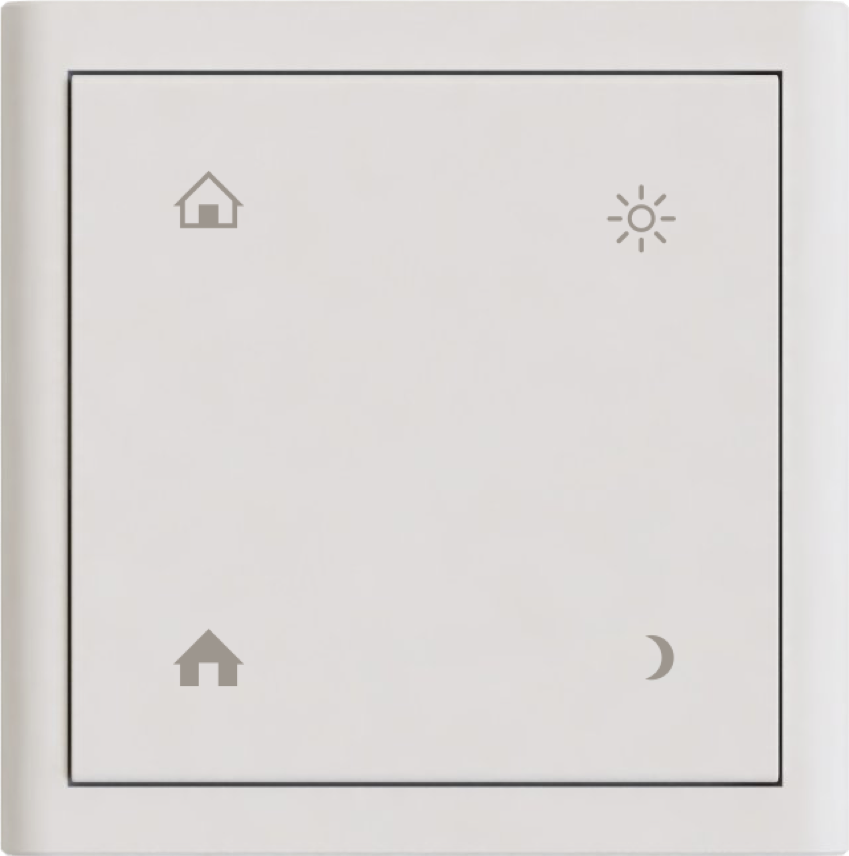
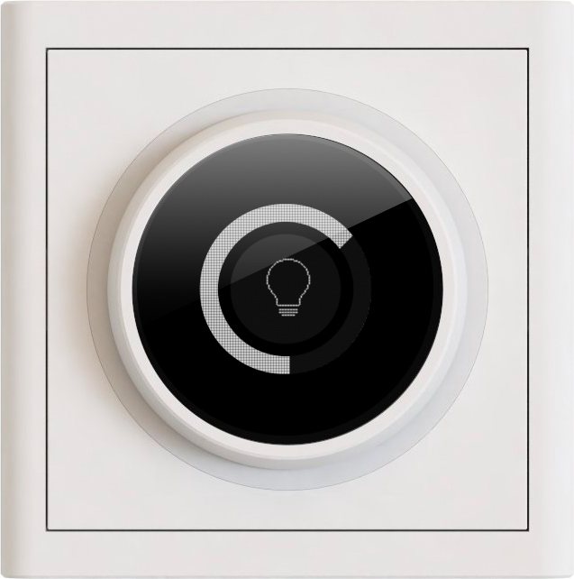
The Multifunction Switch is a Z-Wave Plus mains powered Wallbox mountable Wall Controller. It can be configured to control up to Four separate Light Zones or Central Scenes. Each Light Zone can consist of both Dimmers and Switches. The device can be combined with a Back Unit, which provide local Switch or Dimmer functionality. Room and Floor temperature sensors can also be connected to the device, which enables the device to function as a head-less Thermostat. The Thermostat is fully controllable from a Z-Wave Controller, and can control both a Local and Remote heating relay.
Want to buy adds it to your wish list and follows SE Devices for updates. I own it adds it to your collection.
✅ Future-proofBuilt to keep working — even if the maker walks away.
It works locally over Z-Wave, so it keeps running even if SE Devices shuts down the app or the servers. Nothing here ties you to a single company's survival.
Works locally over Z-Wave — keeps running without the maker's cloud
Still in production
Based on how this device connects (local vs. cloud), whether it’s still sold and supported, and its app / subscription. A guide, not a guarantee.
Connectivity
Z-Wave
Prices
No prices yet — be the first to add one.
Community tags
Be the first to tag this page — tags appear right away. Try a theme, capability, or subject (e.g. WWII, heist, slow burn, time travel, A24).
Community photos
Photos from members
No member photos yet.
Reviews
What members say
Sign in to rate Multifunction Switch and share a photo.
No reviews yet.
Community
Be the first to start a thread about Multifunction Switch
Threads post into the SE Devices community forum.
Sign in to start a thread in the SE Devices community.
Edit history
Loading edit history…
Certified
Firmware
Current version HW: 30 FW: 3.00:03.00
Specifications
Overview
Company
SE Devices
Category
Lighting
Device type
Wall Controller
Connectivity
Standard / protocol
Z-Wave
Connectivity
Z-Wave
Transport
Z-Wave
Spec version
6.71.01
Z-Wave frequency
EU: 869.85MHz, 868.40MHz
Certification & compliance
Certificate ID
ZC10-18026000
Firmware & software
Firmware version
HW: 30 FW: 3.00:03.00
Hardware version
ZM5202
Identity & commercial
Model number
FMS
Lifecycle
Status
Active
More specs
Name
Multifunction Switch
Brand
SE Devices
Features
Feature Values Color
Documents
Category Description File Manual_Primary_Lang
Role type
ROLE_TYPE_SLAVE_ALWAYS_ON
User icon
0x1600
Categories
All Lighting Devices, All Controllers, Lighting Accessories
Product id
0x1002
S2 classes
S2_UNAUTHENTICATED
Device type
Wall Controller
Oem version
HW: 30 FW: 3.00:03.00
Library type
SLAVE_ENHANCED_232
Supports nwi
Yes
Similar Lighting
Current-generation and recently-released alternatives in the same category.
The Multifunction Switch is a Z-Wave Plus mains powered Wallbox mountable Wall Controller. It can be configured to control up to Four separate Light Zones or Central Scenes. Each Light Zone can consist of both Dimmers and Switches. The device can be combined with a Back Unit, which provide local Switch or Dimmer functionality. Room and Floor temperature sensors can also be connected to the device, which enables the device to function as a head-less Thermostat. The Thermostat is fully controllable from a Z-Wave Controller, and can control both a Local and Remote heating relay.
Hardware platform
ZM5202
Short description
Four button Z-Wave Plus Wall Controller for controlling Light Zones, Heating Zones and Central Scenes.
Product identifier
FMS
Countries / regions
European Union
Certification number
ZC10-18026000
Radio range z wave (m)
40
Configuration parameters
Parameter Number Name Description Format Size Min Value Max Value Default Value Parameter Values 5
Supports explorer frames
Yes
Supported command classes
Identifier Name Key Version COMMAND_CLASS_SWITCH_MULTILEVEL
Controlled command classes
Identifier Name Key Version COMMAND_CLASS_THERMOSTAT_MODE
Supported / controlled meter types
Meter Type Rate Type Description Electric meter
Value white thermostat power source value mains powered (120 v/240 v) switch type value push button with indicator z wave scene type value central scene electric load type value incandescent elv (electronic) led dimmable led firmware updatable value updatable by professional/technician supported meter type value electric energy neutral wire required sensors value air temperature power voltage current thermostat modes value heat auxiliary/emergency heat thermostat hvac systems supported value heat only association groups
Group Number Maximum Nodes Supported End Point ID Description 2
From to description 0 32767 safety off period in seconds 17 back unit role configures the role of the back unit, which dictates what local functionality controls it. valid configuration values are: 0 the thermostat will control the back unit (if the back unit is a dimmer, then this value has no effect as thermostats requires a relay to function) 1 the light control feature (buttons) will control the back unit. 2 disconnected mode means the back unit is not controlled by any local ui or features, and can only be controlled via z wave end point 5 (or non channel encapsulated commands). 0 1 0 0 1 from to description 0 2 selected back unit role 80 button led mode controls the operation of the leds. possible values are: 0 – leds are always off (default) 1 – momentary on 2 – stable on the led operation is described in details in the user manual, and also depends on the button mode configuration. 0 1 0 0 0 from to description 0 2 selected led mode 6 safety on period the number of seconds to stay in on mode when safety is activated. the back unit turns back off when the timer have elapsed (and continues to turn on and off alternately). if value is 0, the back unit will not turn on at all. the max limit is 32767 seconds (9 hours, 6 minutes and 7 seconds). a 60 second minimum period applies. 0 2 0 0 300 from to description 0 32767 safety on period in seconds 11 dimmer mode defines if dimmer should operate in leading or tailing edge mode. most lights work quite ok in the default leading edge mode, but this mode also usually cause some noise from the dimmer unit. during installation it is therefore recommended to try te mode, and use this if the light operates properly. tailing edge mode is known to cause instability in some type of lights! this configuration does not have an effect on 1 10 v dimmer back units! 0 = leading edge mode (le) 1 = tailing edge mode (te) 0 1 0 0 0 from to description 0 1 dimmer operation mode 64 temperature report inteval defines the periodic report interval for temperature readings. this can be configured to a minimum of 60 seconds and maximum of (32767 seconds. a 0 value disables the interval based periodic reporting, and any value below 60 results in a 60 second interval. 0 2 0 0 600 from to description 0 32767 report interval in seconds 66 temperature report threshold defines a temperature change threshold where a temperature report is sent regardless of the report interval. this also works if the report interval is disabled. the value is given in 1/10 of a degree celsius, and can be in the range 1 127. a zero value disables the threshold. 0 1 0 0 10 from to description 0 127 report threshold in 1/10th of a degree celcius 240 floor sensor temperature offset defines an offset to the floor temperature, given as a signed integer at 1/10 of a degree celcius. this provides an offset range of –12.8 to +12.7 degrees celcius ( 128 to 127). 0 1 0 0 0 from to description 128 127 temperature offset in 1/10th of a degree celcius 67 thermostat on∕off interval override threshold defines a temperature threshold at which the configured on/off interval is overridden and the heating relay state will change regardless. the value is given in 1/10th of a degree, supporting a max threshold of 12.7 degrees celcius. a zero (0) value disables this feature (the default) 0 1 0 0 0 from to description 0 127 temperature threshold in 1/10th of a degree celcius 241 room sensor temperature offset defines an offset to the room temperature, given as a signed integer at 1/10 of a degree celcius. this provides an offset range of –12.8 to +12.7 degrees celcius ( 128 to 127). 0 1 0 0 0 from to description 128 127 temperature offset in 1/10th of a degree celcius 4 safety activate delay safety mode is activated after the configured number of seconds has elapsed. it will start by turning off the back unit when activated. a 0 value disables safety mode. the max limit is 32767 seconds (9 hours, 6 minutes and 7 seconds). the minimum actication delay is 60 seconds, and values from 1 to 59 will automatically be translated to a 60 second delay. 0 2 0 0 0 from to description 0 32767 safety activate delay in seconds texts