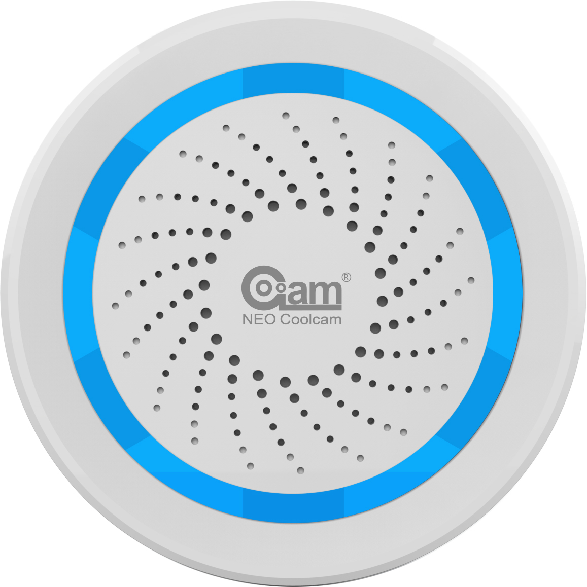
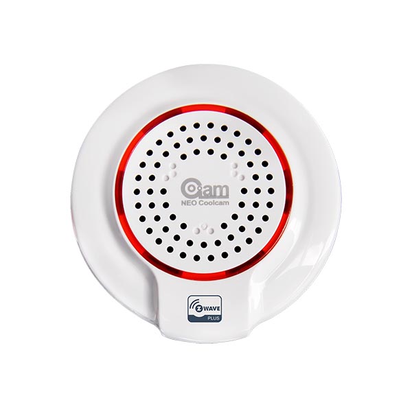
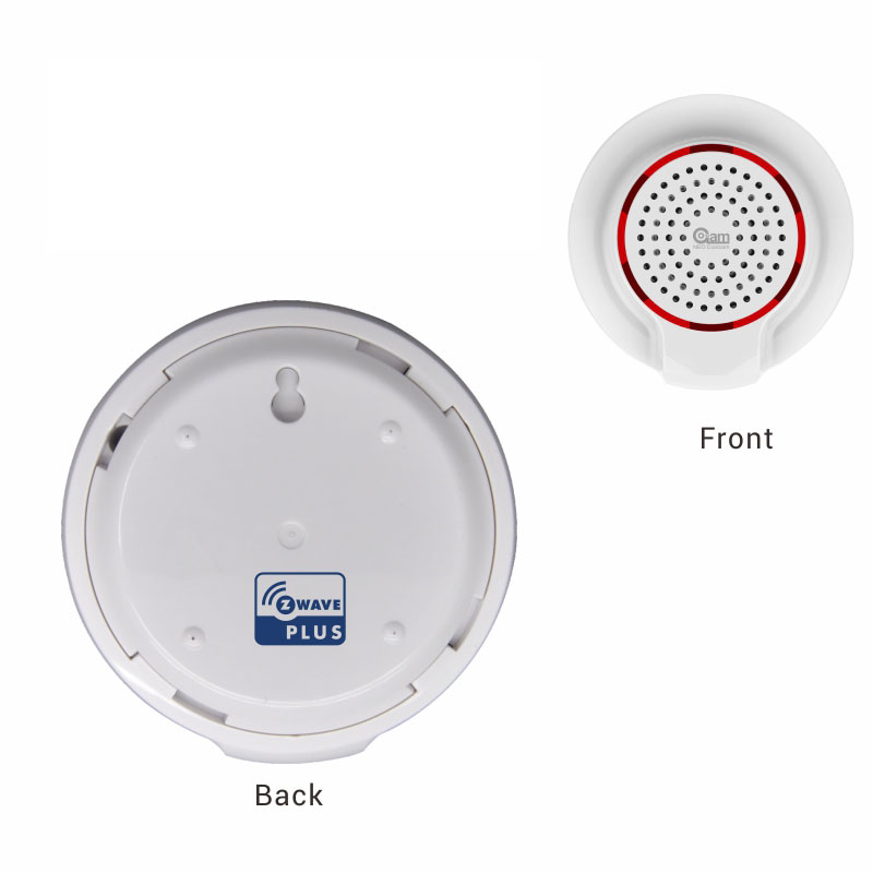
There have two touch buttons on front panel, anyone can be executed inclusion, exclusion and reset from Z-Wave™ network. The device has 2 main functions: Switch and Timing. There are two ways for controlling the wall switch. The one is touch button to turn on/off switch. Another is Z-Wave command class via network. The device also provides the function of timing, and users can turn off the device by opening this function and setting the time cycle, the setting method of which is shown in "Command Class Configuration".
Want to buy adds it to your wish list and follows Coolcam for updates. I own it adds it to your collection.
✅ Future-proofBuilt to keep working — even if the maker walks away.
It works locally over Z-Wave, so it keeps running even if Coolcam shuts down the app or the servers. Nothing here ties you to a single company's survival.
Works locally over Z-Wave — keeps running without the maker's cloud
Still in production
Companion app is actively updated
Based on how this device connects (local vs. cloud), whether it’s still sold and supported, and its app / subscription. A guide, not a guarantee.
Connectivity
Z-Wave
Prices
No prices yet — be the first to add one.
Community tags
Be the first to tag this page — tags appear right away. Try a theme, capability, or subject (e.g. WWII, heist, slow burn, time travel, A24).
Community photos
Photos from members
No member photos yet.
Reviews
What members say
Sign in to rate 2-Channel Wall Switch and share a photo.
No reviews yet.
Community
Be the first to start a thread about 2-Channel Wall Switch
Threads post into the Coolcam community forum.
Sign in to start a thread in the Coolcam community.
Edit history
Loading edit history…
Firmware
Current version HW: 16 FW: 2.33
Specifications
Overview
Company
Coolcam
Category
Sensor
Device type
On/Off Power Switch
Connectivity
Standard / protocol
Z-Wave
Connectivity
Z-Wave
Transport
Z-Wave
Spec version
6.81.01
Z-Wave frequency
EU: 869.85MHz, 868.40MHz
Certification & compliance
Certificate ID
ZC10-19066548
Firmware & software
Firmware version
HW: 16 FW: 2.33
Hardware version
ZM5202
Identity & commercial
Model number
NAS-SC01ZE-2
Lifecycle
Status
Active
More specs
Name
2-Channel Wall Switch
Brand
Coolcam
Features
Feature Values Firmware Updatable
Documents
Category Description File Manual_Primary_Lang
Role type
ROLE_TYPE_SLAVE_ALWAYS_ON
User icon
0x1D02
Categories
Sensors, All Lighting Devices, On/Off Switches/Devices, Network Devices
Product id
0x102B
S2 classes
S2_UNAUTHENTICATED
Device type
On/Off Power Switch
Oem version
HW: 16 FW: 2.33
Library type
SLAVE_ROUTING
Supports nwi
Yes
Similar Sensor
Current-generation and recently-released alternatives in the same category.
There have two touch buttons on front panel, anyone can be executed inclusion, exclusion and reset from Z-Wave™ network. The device has 2 main functions: Switch and Timing. There are two ways for controlling the wall switch. The one is touch button to turn on/off switch. Another is Z-Wave command class via network. The device also provides the function of timing, and users can turn off the device by opening this function and setting the time cycle, the setting method of which is shown in "Command Class Configuration".
Hardware platform
ZM5202
Short description
This product can be included and operated in any Z-Wave™ network with other Z-Wave™ certified devices from other manufacturers and/or other applications.
Product identifier
NAS-SC01ZE-2
Countries / regions
European Union
Supports smart start
Yes
Certification number
ZC10-19066548
Radio range z wave (m)
40
Configuration parameters
Parameter Number Name Description Format Size Min Value Max Value Default Value Parameter Values 5
Supports explorer frames
Yes
Supported command classes
Identifier Name Key Version COMMAND_CLASS_POWERLEVEL
Supported multilevel sensors
Multilevel Sensor Type General purpose
Supported notification types
Notification Type Event / State Access Control
Value updatable by manufacturer outdoor use z wave scene type value scene & central scene communications connections value usb (universal serial bus) communications protocol value manufacturer proprietary protocol loads controlled value 10 supported notification types value access control thermostat power source value mains powered (120 v/240 v) switch type value push button illuminated electric load type value incandescent sensors value motion/no motion (binary) association groups
Group Number Maximum Nodes Supported End Point ID Description 1
From to description 0 0 button switchwill be disabling to turn off 1 1 button switchwill be disabling to turn on 7 channel 1 off time setting this configuration sets the time delay to turn off switch channel 1 when channel 1 is turned on. this configuration is only valid when “configuration no.6” is set to '1'. unit: minute. 0 2 0 0 0 from to description 0 32767 this configuration sets the time delay to turn off switch channel 1 when channel 1 is turned on. 8 channel 2 off time setting this configuration sets the time delay to turn off switch channel 2 when channel 2 is turned on. this configuration is only valid when “configuration no.6” is set to '1'. unit: minute. 0 2 0 0 0 from to description 0 32767 this configuration sets the time delay to turn off switch channel 2 when channel 2 is turned on. 6 timer enable setting this configuration as '1' will start the timing function of the plug, and the length of time is determined by the setting of “configuration: no.7”. this function can only provide the time to turn off device function when the device is open. 0 1 0 0 0 from to description 0 0 turn off the timing function of the plug, 1 1 start the timing function of the plug, 3 relay on/off indicate this parameter defines the relay state. the led will be turn on with pink color when the button is touched to turn on relay if this parameter is set to ‘1’; otherwise the led is off. the default value is ‘1’. 0 1 0 0 1 from to description 0 0 the led is off. 1 1 the led is on 1 relay on/off status saved enable this parameter defines the on/off status of relay is need to save or not. the status will be saved when relay status is changed if this parameter is set to ‘1’; otherwise the relay status is not saved. the wall switch will restore the relay on/off status previous when power on again 0 1 0 0 1 from to description 1 1 the relay status is saved each time it changes so that the relay will return to its previous state after a power failure. 0 0 the relay status is not saved when it changes, so it will not return to its previous state after a power failure. 2 backlight enable this parameter defines the backlight state for touch button. the backlight led is on when wall switch power on if this parameter is set to ‘1’, otherwise the backlight led is off. the default value is ‘1’. 0 1 0 0 1 from to description 1 1 the backlight state for touch button. 0 0 the backlight led is off 4 root device controlled settings this parameter defines which endpoint is mapped to root device (endpoint 0). the valid values are explained as follows. the default value is ‘1’. 1 – endpoint 1 is mapped to root endpoint 3 – both endpoint 1 and 2 are mapped to root endpoint. for example, assumes this parameter is set to ‘1’ (default value). controller or other devices (such as door/window sensor, motion sensor, etc) that associated the wall switch send a command basic set = 0x ff to wall switch, the relay in endpoint 1 will be turned on; other relay status will not be changed. 0 1 0 0 1 from to description 1 1 endpoint 1 is mapped to root endpoint 2 2 endpoint 2 is mapped to root endpoint 3 3 both endpoint 1 and 2 are mapped to root endpoint. texts